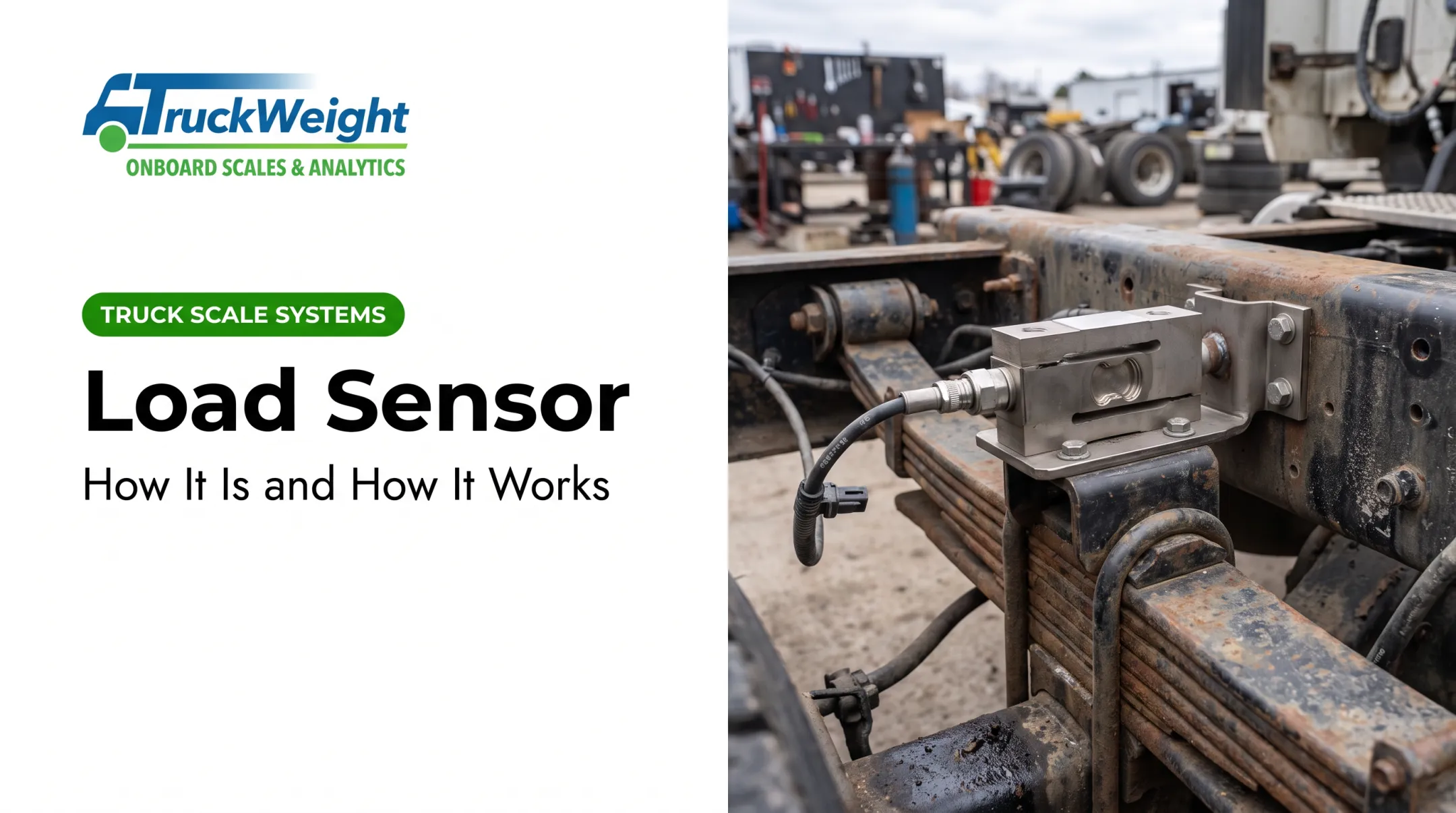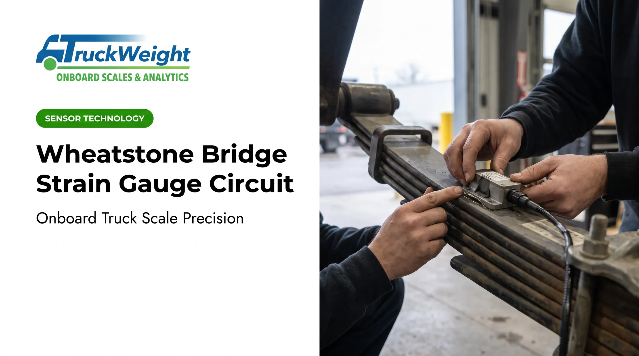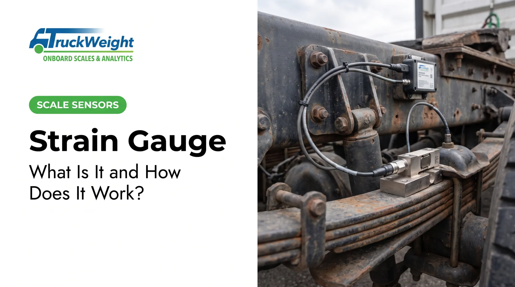

Strain gauge load cells have been the industry's go-to weighing technology since the technology matured in the mid-20th century, and they remain the most common sensor type used in industrial weighing today. Yet many operators and buyers use them daily without understanding what's happening inside.
That gap matters. Misunderstanding the working principle leads to poor sensor selection, sloppy installation, or misread output. This guide breaks down exactly how a strain gauge force sensor works, stage by stage, in plain terms.
Key Takeaways
- Converts mechanical deformation into a measurable resistance change
- Relies on the piezoresistive effect in a metallic foil grid
- Uses a Wheatstone bridge to turn tiny resistance shifts into usable voltage
- Forms the sensing core of load cells, onboard vehicle scales, and structural monitors
- Needs solid installation and temperature compensation to hold real-world accuracy
What Is a Strain Gauge Force Sensor?
A strain gauge force sensor measures force indirectly. It detects the strain, or deformation, that force produces in a host material, then converts that deformation into a change in electrical resistance.
Engineers needed this approach when mechanical springs and manual measurement could not deliver reliable, low-displacement force readings for embedded, continuous monitoring. Bonded resistance gauges solved that gap and remain the standard sensing method.
A strain gauge itself is not a load cell. A strain gauge is the sensing element. A load cell is the complete packaged transducer, housing multiple strain gauges bonded to a spring element (the deformable structural body).
Despite newer piezoelectric and capacitive alternatives, strain gauge sensors still dominate because of their linearity, cost-effectiveness, and proven accuracy across an enormous range of force magnitudes.
Common gauge layouts include:
- Linear: single grid, one direction of strain
- Rosette: multiple grids for multi-directional strain
- Diaphragm: matched to circular pressure-sensing elements
- Torsion/shear: angled grids for twisting forces
- Dual-parallel: two grids, common on bending beams
The physical layout changes to match the strain direction being measured, but the underlying resistance-change principle stays identical across all five.

How Does a Strain Gauge Force Sensor Work?
The sensor operates through a defined sequence: force application, deformation, resistance change, signal conditioning, and output. Each stage is outlined below.
Force Application
The process starts when an external force, load, or pressure hits a spring element, the deformable structural component the strain gauge is bonded to.
This initiation is continuous and condition-based, not manually triggered. The sensor responds passively whenever load is present, whether that's a truck axle bearing weight or a beam under stress.
A common bottleneck happens here, before any signal exists. Improper bonding or misalignment between the gauge and the spring element introduces measurement errors from the first moment.
TruckWeight's SG sensor install shows why prep matters: technicians grind and sand the mounting surface, clean it repeatedly with isopropyl alcohol, and bond the gauge at 70°F or warmer. Skip that step, and every downstream reading inherits the error.
Deformation and Resistance Change
As the spring element deforms under load, the bonded metallic foil grid stretches or compresses right along with it. That mechanical coupling is the operating principle.
This physically alters the length and cross-sectional area of the conductive grid, producing a resistance change proportional to the strain. The relationship is governed by:
ΔR/R = K · ε
Where K is the gauge factor and ε is strain. For metallic foil strain gauges, HBM cites a typical gauge factor around 2.0 for Constantan foil and 2.2 for Modco foil, depending on grid material.
The accuracy and linearity of the output signal depend directly on:
- Gauge material quality
- Bonding integrity
- Grid orientation relative to strain direction
Get any of these wrong, and the sensor reports strain that doesn't match reality.

Wheatstone Bridge and Signal Conditioning
The resistance change from strain is tiny, often in the range of 10⁻⁴ to 10⁻² ohm per ohm. That's far too small to read directly, so engineers use a Wheatstone bridge circuit to detect and amplify it into measurable voltage.
Three bridge configurations are common:
| Configuration | Active gauges | Temperature compensation |
|---|---|---|
| Quarter-bridge | 1 | Not automatic; requires external dummy gauge |
| Half-bridge | 2 | Well compensated |
| Full-bridge | 4 | Highest sensitivity, best common-mode rejection |
Full-bridge setups generally win on sensitivity and thermal stability when the mechanical design supports four matched gauges.
Temperature compensation matters because thermal expansion mimics real force. Unregulated heat causes "apparent strain," a resistance shift that looks like a load change but isn't. Compensating resistors or matched gauge pairs cancel this effect.

That stability requirement is also why TruckWeight builds SG sensors waterproof and corrosion-resistant for the temperature swings fleets see every day.
Measurable Force Signal
The bridge produces an output voltage, typically in the millivolt range (often expressed as mV/V of excitation). A signal conditioner or amplifier then amplifies, filters, and digitizes that signal.
This digital or analog output feeds into downstream systems:
- Weight indicators
- Data loggers
- Fleet telematics platforms
A well-compensated, properly calibrated sensor delivers repeatable, drift-free readings. That reliability supports decisions like load balancing before a shipment leaves the yard or confirming compliance before hitting a scale.
TruckWeight's SG-2 sensor, for example, feeds axle-group and gross-vehicle-weight data to a handheld display or TruckWeight Analytics—so drivers and fleet managers get a usable number instead of raw voltage.
Where Strain Gauge Force Sensors Are Used
Strain gauge force sensors show up in several distinct applications:
- Industrial weighing - embedded in load cells for platform scales, hoppers, and process weighing
- Vehicle payload monitoring - bonded to suspension components to estimate axle and gross vehicle weight
- Structural stress analysis - mounted on beams, bridges, and machine frames for ongoing monitoring
These sensors work best in stable-to-moderate temperatures under static or slowly changing loads. Rugged designs can still hold linearity under dynamic and shock loads, but extreme vibration or rapid load reversal can challenge less robust units.
In commercial trucking, strain gauge sensors are commonly used on spring (mechanical) suspensions to estimate axle and gross vehicle weight. TruckWeight's SG-1 and SG-2 sensors are built for this application:
- SG-1: front-axle strain gauge for mechanical suspensions
- SG-2: spring trailers, drive axles, walking-beam suspensions, and Chalmers systems—typically within 0.3% to 2% of gross vehicle weight
Both are wireless, waterproof, shock-resistant, and installable in minutes without special tools. They give fleets on mechanical-suspension trucks, tractors, and trailers onboard payload visibility without complex wiring.

Conclusion
A strain gauge force sensor works by translating physical deformation into a tiny, measurable resistance change, then amplifying that change through a Wheatstone bridge into a usable voltage signal. The idea is straightforward; accurate, repeatable results still depend on solid design and setup.
That signal chain drives the choices that matter: bridge configuration, careful installation, and rugged, pre-calibrated systems built for field conditions like commercial trucking. Get those right, and you get weight data you can act on—not a black box on the suspension.
Frequently Asked Questions
How does a strain gauge force sensor work?
Force deforms a spring element, which stretches or compresses a bonded metallic foil grid. That deformation changes the grid's resistance, which a Wheatstone bridge converts into a measurable voltage signal.
How do you use a strain gauge to measure force?
Bond the gauge to a spring element, wire it into a Wheatstone bridge, then calibrate the system so resistance changes correlate to known force values. Signal conditioning turns that into a usable output.
What is the difference between a strain gauge and a load cell?
A strain gauge is the sensing element itself. A load cell is the complete packaged transducer, typically containing four strain gauges bonded to a spring element and wired into a bridge.
Why is temperature compensation important in strain gauge sensors?
Heat causes thermal expansion that mimics real strain, called "apparent strain." Compensating resistors or matched gauge pairs cancel this effect, preventing false readings.
What is a Wheatstone bridge and why is it used with strain gauges?
A Wheatstone bridge detects the extremely small resistance changes a strain gauge produces and converts them into a measurable differential voltage. Without it, the signal would be too weak to use.
How accurate are strain gauge force sensors in real-world conditions?
Accuracy depends heavily on installation quality, calibration, and temperature compensation, not just the gauge itself. TruckWeight's SG-2 sensor, for example, is rated within 0.3% to 2% of gross vehicle weight under real fleet conditions.